ON Axis parabolic mirrors are the central part of the surface of a paraboloid of revolution. The figure below shows the names of the parameters, used in the description of on axis parabolic mirrors.
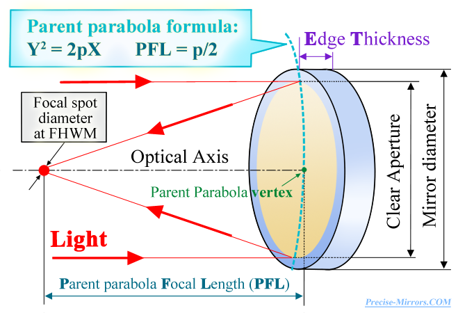
The main property of a paraboloid: the ray emerging from its focus after reflection from its surface will move parallel to the optical axis of the paraboloid. Thus, axial parabolic mirrors make it possible to obtain a collimated beam from a point source located on the optical axis the reflecting mirror itself (while for an off-axis parabola the source is always located outside the optical axis of the mirror itself). Scheme of operation of an axial parabola is axisymmetric (while the off-axis parabola has a non-axisymmetric scheme).
With an increase in the radiation power that the mirror reflects, at some point at a certain threshold value power, the reflective coating is destroyed (or, for example, the substrate surface of the mirror itself, if there is no coating). This value is called the "damage threshold" of the mirror (in English they usually write L. I. D. T.). It can be indicated in units of power per unit area, but for pulsed radiation it is customary to indicate it as units of energy per surface area unit for a pulse with certain duration. For example, if the breakdown threshold for a mirror is specified as 10 J/cm2 (for a 10 ns pulse), this means that every square centimeter of this mirror can reflect a pulse with a duration of 10 ns and an energy of 10 J.
The exact value of the damage threshold (L.I.D.T.) depends on:
--- the mirror itself (type of reflective coating, quality of coating and manufacturing of the mirror) and
--- radiation parameters (pulse energy, their duration and repetition rate, spectral range, size of the irradiated
areas, duration of irradiation and some other factors.
Mirrors with dielectric coating have the highest damage threshold (high LIDT),
average typical values for dielectric coatings are:
--- for pulsed radiation 10-20 J/cm2 (λ=1064 nm, 10 ns, 10 Hz, irradiation 1 mm2) and
--- for continuous radiation approximately 3-20 kW/cm2 (λ=1064 nm, irradiation 1 mm2).
Mirrors with a metal coating (but not the metal backing of the mirror itself) have a noticeably lower
damage threshold (lower LIDT), average typical values for metal coatings are:
--- for pulsed radiation 0.5-2 J/cm2 (λ=1064 nm, 10 ns, 10 Hz, irradiation 1 mm2) and
--- for continuous radiation approximately 0.5-1 kW/cm2 (λ=1064 nm, irradiation 1 mm2).
Using various methods, it is possible to obtain higher damage threshold values (better LIDT), e.g.
for dielectric mirrors:
--- for continuous radiation it is possible to achieve 50-150 kW/cm2 (λ=1064 nm) and
--- for pulsed radiation it is possible to achieve 70-90 J/cm2 (pulses 10 ns, λ=1064 nm).
IMPORTANT! If you change the radiation wavelength, pulse duration, or size of the irradiated area the value of the damage threshold changes strongly and nonlinearly.. Moreover, with a sufficiently large change even one of the radiation parameters (for example, pulse duration), a model of the interaction of radiation with the coating of the mirror will fundamentally change, which can change the value of the damage threshold by several orders of magnitude in one direction or another. Therefore, it is very important that a specialist assess the damage threshold for your task.
Axial parabolic mirrors are most often used for two purposes.
The first task is the work of one mirror, which either focuses the collimated beam to a point, or vice versa
creates a collimated beam from radiation diverging from a point source. It is theoretically possible to use
pairs of conjugate parabolic mirrors (with different focal lengths), as a result of which, first from a point
source, a collimated beam will be formed, and then it will be focused back to a point (in essence, this is an image of the source).
But in practice, for this scheme they often use
OFF axis parabolic mirrors
.
The second task is to work as the main radiation-collecting mirror in one of the classical telescope designs.
In this case, very often in the center of such a mirror there is a small hole through which the radiation collected by this mirror
(after reflection from another small mirror) reaches the observer.
| Mirror minimal and maximal sizes: | from 40 mm to 1200 mm | |
| Mirror substrate material: | Astrositall, by request: Zerodur, UV FS, Si and other. | |
| Coatings: | Metallic (Ag, Au, Al) and special EUV|XUV. | |
| Manufacture accuracy (RMS, λ=633 nm) | Base | Maximal |
| surface shapes, aspherical mirrors | up to λ/40 | up to λ/150 |
| Radiuses manufacture accuracy | up to ±0.1% | up to ±0.05% |
| Surface microroughness, RMS | 0.3 nm | 0.15 нм |
| Cosmetic quality (per square inch) | 60/40 scratch/dig | 10/5 scratch/dig |
The main advantage of on-axis parabolic mirrors is that they virtually have no aberrations at all (at least from a practical
point of view) Thus, with sufficiently good accuracy in manufacturing the shape of the reflective surface, the result will be determined
by diffraction limitations optical design.
The main disadvantage of on-axis parabolic mirrors is that when we are talking about precision and ultra-precision mirrors
(λ/30-λ/150 RMS), then their production is extremely labor-intensive and requires high costs (especially for mirrors with
large asphericity), and accordingly the cost and timing supplies of such mirrors are noticeably larger than for conventional spherical
optics (even if they are also very accurate).
Typically, it is very important for the customer how small a spot in the image plane can be formed by the mirror (see figure below). Even if the task is to obtain a collimated beam or construct an image, the value of the minimum focused spot size allows You to evaluate the quality (for example, divergence) of the resulting collimated beam or image (resolution).
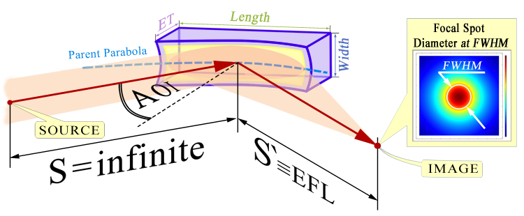
The size of the spot in the image plane can be influenced by many different factors, but from actual practice these are mainly spherical aberrations, manufacturing precision of the mirror surface shape, and sometimes diffraction limitations at the operating wavelength. Also, the accuracy of the adjustment is often extremely important, since sometimes for example, an error in mirror position of just a few microns can increase the diameter of the focused spot several times.
The general principle is that the closer the size of focused spot
to the diffraction limit, the more expensive such a mirror is.
It depends on your task and the funds allocated for the purchase. The most competent and correct way would be to fill out our special "request form". It is also advisable to attach to the request form a description of your optical design (at least in words) in which the mirror will operate (especially if we are talking about the operation of two requested mirrors in a paired pair) and send all this to our e-mail quote@precise-mirrors.ru. Next, our specialists will select several suitable options for you (see example of a typical quote for single mirrors or for two conjugate mirrors ).
You can also send a detailed exact specification of the mirror you need with drawings, a description of the type of surface shape, calculated constants, with all tolerances, etc. But even in this case, it is better to add at least minimal information on your optical design, We may be able to offer some improvements to the specification of your mirror. In this case, the customer does not bear any additional expenses.
You also don’t have to fill out "request form" , and do not send a detailed exact specification of the mirror you need, but instead send a description of Your task (mirror) in any form to the same email address quote@precise-mirrors.ru. But in this case, such a request may take much longer to process.